

I built a clock.
That sentence doesn't deserve a blog post. Let me try again.
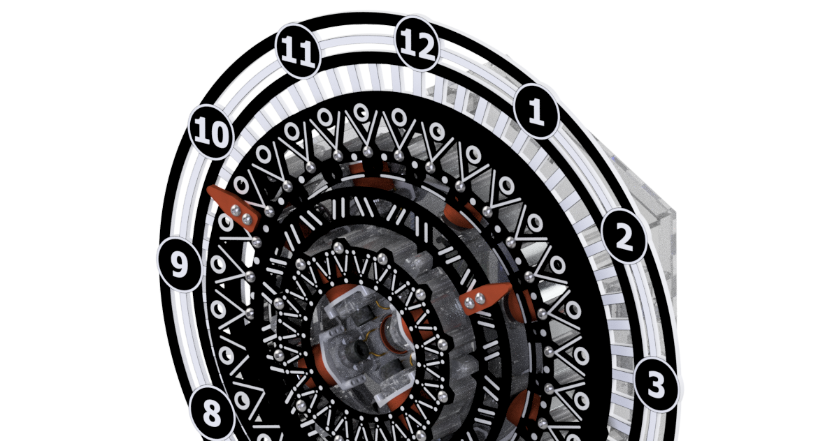
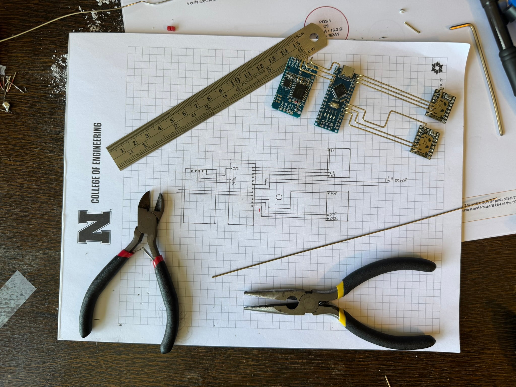
I designed and built a clock that has no gears. No quartz movement. No commercial parts inside, beyond the bearings and the off-the-shelf chips that drive it. Two concentric rings of neodymium magnets float on their own bearing races, driven directly by twelve electromagnetic coils that I hand-wound on machined steel cores. The wiring isn't on a circuit board — it's polished brass rod, bent and soldered into deliberate paths through the inside of a clear acrylic case so the wiring itself becomes part of the visible aesthetic.
That's better.
The whole thing came out of my own ideas and my own bench
I designed every part. Every CAD model. The electromagnetic geometry was derived from first principles for this specific application, not adapted from a reference design. The fifth full iteration of the CAD ("MK5") is what got fabricated. The firmware is mine. The PCBs aren't PCBs at all because I made the wiring sculptural - but the schematic is mine and so are the wiring detail drawings and the stator layouts. I wound every one of the twelve coils on a hand drill while watching an ohmmeter, and I built the controller from individual brass bars I cut and bent to fit.
There were people I asked questions of, including my professor, who I owe specifically for talking me out of designing my own bearing (more on that in a minute). But the build is mine top to bottom.
What the thing actually does
It's a clock. It tells time.
A normal analog clock has a tiny stepper motor and a 1:30 reduction gear train between the hands. I deleted both of those. The minute hand is a ring of sixty alternating-polarity neodymium magnets that rotates on its own thin-section bearing. The hour hand is the same idea with twelve magnets on a smaller ring inside the minute ring. Each ring sits on top of a stationary stator: eight coils for the minute, four for the hour, arranged in two-phase stepper geometry so that energizing the right coils at the right moment advances the ring by exactly one position.
The math worked out cleanly: every electrical cycle of the stator advances the rotor by one magnet pitch. The minute ring needs to advance once per minute, the hour ring once per hour, and that's it. No reduction. No gears. The hand moves directly because the magnet attached to it moves directly.
A nice consequence of the way I picked the magnet and coil counts: the rings have strong cogging detents. When the coils aren't powered, the magnets find the nearest stable position and lock in. For a continuously-rotating motor that would be a defect. For a clock that only needs to advance once a minute, it's a feature — the rings hold position with no current at all, so the controller can de-energize the coils between steps and just go back to sleep.
The greatest hits of things that didn't work the first time
The bearing. I tried to design my own. My professor (rightly) talked me down from this within thirty seconds: the angular tolerance achievable on a desktop CNC was never going to match what the rotor needs to hold position under detent torque. Five iterations later I landed on a self-tensioning race that uses commercial 608 ball bearings as the precision element. Lesson: tolerance from precision parts is a thousand times cheaper than tolerance from manufacturing skill.
The coils. Three attempts. The first used super glue and an aerosol activator on the recommendation of someone who had wound a lot more coils than me and assured me the chemistry wouldn't dissolve the wire's enamel insulation. It dissolved the wire's enamel insulation. The second attempt used no adhesive at all and the wire packing was, charitably, a disaster. The third attempt finally worked: 388 electrical-grade silicone applied every few layers, single-component cure, easy to rework, no thermal expansion concerns for this application.
The stator. Three SLA print orientations. First as two halves bonded together, which didn't align cleanly. Then printed vertically because the slicer recommended it, which produced terrible tolerance in the bearing seat thanks to the layer-line orientation. Finally printed horizontally against the slicer's advice, which kept the supports out of the dimensionally critical features. That's the version that worked.
The clock face. Four laser-etching iterations before the painted-and-etched numerals came out clean.
The enclosure. First attempt with two-part epoxy gave me cloudy bond lines and squeeze-out staining the inside of the panels. Second attempt cured clear UV resin through the acrylic with a UV lamp, and the joints are now optically near-invisible.
The brass freeform circuit. Took about an entire weekend of unbroken work. I will not be itemizing the hours.
A small fact I'm fond of
The motor driver chips have a sleep mode. The microcontroller has a sleep mode. The real-time clock chip emits a one-Hertz pulse on its own. Put those facts together and the clock spends fifty-nine seconds out of every minute completely asleep, drawing essentially no current, and wakes up only when there's a hand to advance. Then it goes right back to sleep.
For the geometry-loving among you: the cogging detents I mentioned earlier hold the ring in position during that sleep window. The microcontroller doesn't have to do anything during the fifty-nine seconds. The magnets remember where they were.
What's next
The build is mechanically and electrically complete. The cogging works (and I'll happily demonstrate it by hand to anyone within arm's reach). The firmware is written and ready to flash. What I haven't done yet, but will, is the actual integrated power-on and the twenty-four-hour drift test that turns "this should keep time" into "I measured the drift and have the data." That's the next milestone.
I'd also love a third ring for a second hand someday. And a custom PCB that preserves the brass aesthetic instead of replacing it.
But for now: I designed and built this clock from a pile of magnets, some steel bolts, a length of wire, a couple of off-the-shelf chips, and the contents of my own head. It's quietly satisfying.
Designed and built solo. Photos from my workbench. CAD MK5 in Inventor, firmware in Arduino C++, drawings in drawio, fabrication on a hodgepodge of equipment from the Nebraska Innovation Studio makerspace at UNL.


